Frequency converters provide significant benefits when used together with ABB process performance motors. The advantages include better process control and energy savings through regulation of motor speed, and smooth starting with reduced inrush current, reducing the stress on the equipment and supply network.
By choosing an ABB motor–drive package, users can be confident that the motor and drive combination is optimized for their application; it is a working package with known performance, as the combination has been tested and verified.
Process performance motors are designed for both DOL and variable-speed operation, and will, either as standard or by adding a few extras, be suitable for variable-speed operation.
When selecting process performance motors for VSDs, the following points must be taken into consideration. The DriveSize selection software available at www.abb.com helps in selecting the optimal combination of motor, drive and supply transformer.
Operating speed
Process performance motors are designed to work over a wide speed range and also at speeds significantly higher than nominal. The maximum speeds can be found on motor rating plates or in DriveSize. In addition to motor speed, make sure that the maximum or critical speed of the entire application is not exceeded.
Guideline maximum speed values for process performance motors are shown in Table 1.
Maximum speed, r/min
Motor size 2-pole motors 4-pole motors
71-80 6000 4000
90-100 6000 6000
112-200 4500 4500
225-250 3600 3600
280 3600 2000
315 3600 2200
355 SM, ML, LKA3600 2200
355 LKB 3000 2200
400 3600 2200
450 3000 2200
Table 1. Guideline maximum speed values for process performance motors.
Ventilation
When the motor is operating at low speeds, the cooling capacity of the fan decreases, which again reduces the motor’s load capacity. A separate, constant-speed fan (variant codes 183, 422, 514) can be used to increase cooling capacity at low speed if required for loads with constant torque characteristics.
Lubrication
The lubrication interval of regreasable bearings depends on the running speed of the motor and the bearing temperature. Motors in frame size 280 and larger are delivered as standard with a lubrication plate in tabular format that states the relubrication intervals at different speeds and temperatures. A similar plate is optional for sizes 160–250 and can be ordered using variant code 795. Smaller motors usually have greased, sealed-for-life bearings. Please refer to the installation, operation and safety manual for further information on lubrication.
Winding insulation
To ensure that motors operate reliably, the effects of non-sinusoidal output voltages from the converter must be taken into consideration when selecting the correct insulation system for the motor and output filters for the converter. The insulation and filters must be selected according to Table 2.
Winding insulation and filters required
UN ≤ 500 V Standard insulation
UN ≤ 600 V Standard insulation + dU/dt
filters OR Special insulation
(variant code 405)
UN ≤ 690 V Special insulation (variant
code 405) AND dU/dt-filters at
converter output
600 V < UN ≤ 690 V cable
length > 150 m Special insulation (variant code 405)
Table 2. Selection of motor winding insulation and converter output filters
For more information on dU/dt filters, see the relevant ABB drives catalogs.
For other converters and cases where the guidelines shown in Table 2 cannot be applied, selection must be based on the voltages present at the motor terminals.
01 Maximum allowed phase-to-phase voltage peaks at motor terminals, as a function pulse rise time.
Allowed phase-to-ground voltage peaks at motor
terminals:
– 1,300 V peak: standard insulation
– 1,800 V peak: special insulation, variant code 405
The maximum allowed phase-to-phase voltage peaks at the motor terminals as a function of pulse rise time are shown in Figure 01. The higher curve (special insulation) applies to motors with special winding insulation for frequency converter supply (variant code 405). Standard insulation applies to motors with a standard design.
Bearing currents
Bearing voltages and currents must be avoided in all motors to ensure reliable operation of the entire application. Table 3 gives the selection rules depending on motor output power and frame size when used together with ABB converters; the same rules can also be applied as guidance when using ABB process performance motors with other converters.
Nominal power (PN and / or
Frame size (IEC) Precautionary measures
PN < 100 kW No action needed
PN ≥ 100 kW OR IEC 315 ≤
Frame size ≤ IEC 355 Insulated non-drive end bearing
PN ≥ 350 kW OR IEC 400 ≤
Frame size ≤ IEC 450 Insulated non-drive end bearing AND Common mode filter at the converter
Table 3. Precautionary measures to avoid bearing currents in variable speed drives.
Common mode filters
Common mode filters are installed at the output of the frequency converter. These filters reduce common mode currents and so decrease the risk of bearing currents. Common mode filters do not significantly affect the phase of main voltages on motor terminals. For more information, see ABB drives catalogs.
Insulated bearings
ABB uses bearings with an insulated outer race or hybrid bearings with ceramic rolling elements. Insulated bearings at the non-drive end should be selected as indicated in Table 3. This solution can be ordered using variant code 701.
Earthing and cabling
For motors with a nominal power above 30 kW, cables with a symmetrical concentric protective earth should be used across the system. The same type of cables are also recommended for motors with an output of 30 kW and below.
Solutions for persistent bearing currents
In very rare cases, bearing currents might still exist even if the measures specified above have been taken. For such installations, there are two advanced methods that would provide a remedy: either a shaft grounding bush, or insulated bearings at both ends.
The shaft grounding bush is installed inside the motor to protect it from the environment and ensure good grounding of the shaft. The shaft grounding brush can be ordered using variant code 588.
The second advanced solution is to mount insulated bearings at both ends. These can either be bearings with an insulated out race, or hybrid bearings with ceramic rolling elements. Insulated bearings at both ends can be ordered using variant code 702. Note that this variant cannot be combined with special drive-end bearing solutions, such as roller bearings or angular contact ball bearings.
Electromagnetic compatibility (EMC)
The high-frequency components in a variable speed drive might cause electromagnetic interference with other equipment in the installation. To avoid this, certain measures should be taken. To meet EMC requirements, special EMC cables glands with a 360° connection to the concentric protective earth conductor should be used. Such cable glands can be used with variant code 704.
Motor loadability with frequency converter drives
The difference in the temperature rise of a motor run direct on line compared to the same motor run with a converter is influenced by factors such as the cooling effect of a shaft-mounted fan depending on the speed of the motor, increased losses due to harmonics generated by the converter and reduced flux above the field weakening point. The effects of all these factors are combined in the loadability curves.
The loadability curves shown in Figures 02-05 are generic and give indicative guidelines for dimensioning standard low-voltage motors used with a frequency converter.
The curves show the maximum continuous load torque as a function of frequency (speed), which results in the same temperature rise as operation with the rated sinusoidal supply at nominal frequency and full rated load.
Normally, process performance motors operate according to a class B temperature rise. For these motors, dimensioning should be according to the temperature rise B curve, or the motor can be slightly overloaded. In other words, it can be dimensioned according to the temperature rise F curve. However, if only a class F temperature rise with a sinusoidal supply is indicated for the motor in the technical data section, dimensioning must be done according to temperature rise curve
If the motor is loaded according the temperature rise F curve, it will be necessary to check the temperature rise in other parts of the motor and ensure that the lubrication intervals and grease type are still appropriate.
Low voltage Process performance cast iron motors
18 Ordering information
19 Rating plates
20 Technical data IE2
37 Technical data IE3
50 Technical data IE4
56 Variant codes
63 Mechanical design
63 Motor frame and drain holes
66 Bearings
77 Terminal box
86 Dimension drawings
86 IE2 cast iron motors
88 IE3 cast iron motors
90 IE4 cast iron motors
91 Accessories
91 Built-in brake
94 Separate cooling
96 Silencer
97 Slide rails
99 Cast iron motors in brief
102 Motor construction
Ordering information
Explanation of the product code
Motor type Motor size Product code Mounting arrangement code, Variant codes
Voltage and frequency code,
Generation code
M3BP 160MLA 3GBP 161 410 - ADG 003,etc.
1234 567 891011121314
Positions 1 to 4
3GBP Totally enclosed fan cooled squirrel cage motor with cast iron frame
Positions 5 and 6
IEC size IEC size
07: 71 20: 200
08: 80 22: 225
09: 90 25: 250
10: 100 28: 280
12: 112 31: 315
13: 132 35: 355
16: 160 40: 400
18: 180 45: 450
Position 7
Speed (Pole pairs)
1: 2 poles
2: 4 poles
3: 6 poles
4: 8 poles
5: 10 poles
6: 12 poles
7: > 12 poles
8: Two-speed motors for fan drive motors for constant torque
9: Multi-speed motors, two-speed
Positions 8 to 10
Serial number
Position 11
-(dash)
Position 12 (marked with black dot in data tables)
Mounting arrangement
A: Foot-mounted, top-mounted terminal box
R: Foot-mounted, terminal box RHS seen from D-end
L: Foot-mounted, terminal box LHS seen from D-end
B: Flange-mounted, large flange
C: Flange-mounted, small flange (sizes 71 to 112)
H: Foot- and flange-mounted, terminal box top-mounted
Position 12 (marked with black dot in data tables)
J: Foot- and flange-mounted, small flange with tapped holes
S: Foot- and flange-mounted, terminal box RHS seen from D-end
T: Foot- and flange-mounted, terminal box LHS seen from D-end
V: Flange-mounted, special flange
F: Foot- and flange-mounted. Special flange
Position 13 (marked with black dot in data tables)
Voltage and frequency
Single-speed motors
B: 380 VΔ 50 Hz
D: 400 VΔ, 415 VΔ, 690 VY 50 Hz
E: 500 VΔ 50 Hz
F: 500 VY 50 Hz
S: 230 VΔ, 400 VY, 415 VY 50 Hz
T: 660 VΔ 50 Hz
U: 690 VΔ 50 Hz
X: Other rated voltage, connection or frequency, 690 V maximum
Position 14
Generation code
A, B, C...G...K: The product code must be, if needed, followed by variant codes.
Efficiency values are given according to IEC 60034-2-1; 2014
For detailed dimension drawings please see our web-pages ‘www.abb.com/motors&generators’ or contact ABB.
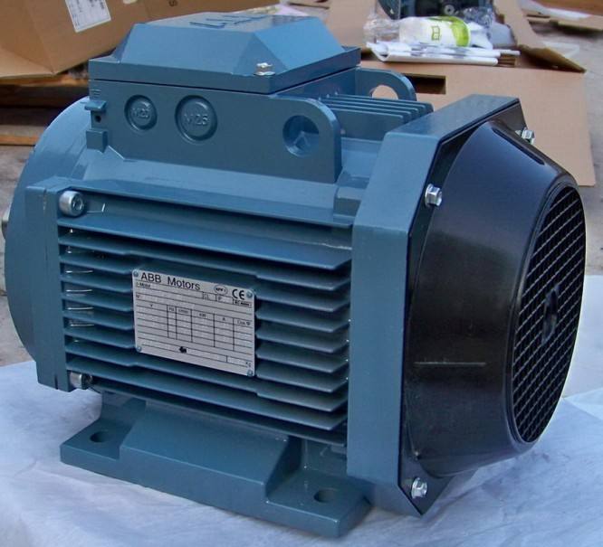
Rating plates
01 Rating plate example, motor size 100, IE2.
02 Rating plate example, motor size 160, K generation, IE3.
03 Rating plate example, motor size 315, L generation, IE3.
04 Rating plate example, motor size 315, IE4.
The motor’s main rating plate shows the motor’s performance values with various connections at nominal speed. The rating plate also shows the efficiency level (IE2, IE3, or IE4), year of manufacture, and the lowest nominal efficiency at 100, 75, and 50 % nominal load.
The plate samples shown on this page present typical data rows. The actual content of the plate may vary according to your order and according to the motor’s IE class.
Technical data, 400 V 50 Hz
IE2 cast iron motors
IP 55 - IC 411 - Insulation class F, temperature rise class B
IE2 efficiency class according to IEC 60034-30-1; 2014
| Efficiency IEC 60034-30-1; 2014 |
Current | Torque | ||||||||||||||
| Output kW |
Motor type | Product code | Speed r/min |
Full load 100% |
3/4 load 75% |
1/2 load 50% |
Power factor Cosj |
IN A |
IS/IN | TN Nm |
TI /TN | Tb/TN | Moment of inertia J = 1/4 GD2 kgm2 |
Weight kg |
Sound pressure Level LPA dB |
|
| 3000 r/min = 2 poles | 400 V 50 Hz | CENELEC-design | ||||||||||||||
| 0.37 | M3BP 71MA 2 | 3GBP071321-••B | 2768 | 74.8 | 75.4 | 72.4 | 0.78 | 0.89 | 4.5 | 1.27 | 2.2 | 2.3 | 0.00039 | 11 | 58 | |
| 0.55 | M3BP 71MB 2 | 3GBP071322-••B | 2813 | 77.8 | 78.3 | 76 | 0.79 | 1.29 | 4.3 | 1.86 | 2.4 | 2.5 | 0.00051 | 11 | 56 | |
| 0.75 | M3BP 80MB 2 | 3GBP081322-••B | 2895 | 80.6 | 79.6 | 75.6 | 0.74 | 1.8 | 7.7 | 2.4 | 4.2 | 4.2 | 0.001 | 16 | 57 | |
| 1.1 | M3BP 80MC 2 | 3GBP081323-••B | 2870 | 81.8 | 81.7 | 78.9 | 0.8 | 2.44 | 7.5 | 3.63 | 3.7 | 4.6 | 0.0012 | 18 | 60 | |
| 1.5 | M3BP 90SLB 2 | 3GBP091322-••B | 2900 | 82.2 | 82.9 | 81.3 | 0.87 | 3.26 | 7.5 | 4.9 | 2.5 | 2.6 | 0.00254 | 24 | 69 | |
| 2.2 | M3BP 90SLC 2 | 3GBP091323-••B | 2885 | 83.2 | 85.5 | 84.3 | 0.88 | 4.2 | 6.8 | 7.2 | 1.9 | 2.5 | 0.0028 | 25 | 64 | |
| 3 | M3BP 100LB 2 | 3GBP101322-••B | 2925 | 85.2 | 84.9 | 82.7 | 0.87 | 5.75 | 9.1 | 9.7 | 3.1 | 3.5 | 0.00528 | 36 | 68 | |
| 4 | M3BP 112MB 2 | 3GBP111322-••B | 2895 | 86.1 | 87 | 86.6 | 0.89 | 7.52 | 8.1 | 13.1 | 2.9 | 3.2 | 0.00575 | 37 | 70 | |
| 5.5 | M3BP 132SMB 2 | 3GBP131322-••B | 2865 | 87.7 | 88.4 | 87.7 | 0.86 | 10 | 7 | 18.3 | 2.6 | 2.7 | 0.0128 | 68 | 70 | |
| 7.5 | M3BP 132SMC 2 | 3GBP131324-••B | 2890 | 88.2 | 88.8 | 87.6 | 0.89 | 13.7 | 7.3 | 24.9 | 2.6 | 3.6 | 0.0136 | 70 | 70 | |
| 11 | M3BP 160MLA 2 | 3GBP161410-••G | 2938 | 90.6 | 91.5 | 91.1 | 0.9 | 19.2 | 7.5 | 35.7 | 2.4 | 3.1 | 0.044 | 127 | 69 | |
| 15 | M3BP 160MLB 2 | 3GBP161420-••G | 2934 | 91.5 | 92.4 | 92.2 | 0.9 | 26 | 7.5 | 48.8 | 2.5 | 3.3 | 0.053 | 141 | 69 | |
| 18.5 | M3BP 160MLC 2 | 3GBP161430-••G | 2932 | 92 | 93.1 | 93.1 | 0.92 | 31.5 | 7.5 | 60.2 | 2.9 | 3.4 | 0.063 | 170 | 69 | |
| 22 | M3BP 180MLA 2 | 3GBP181410-••G | 2952 | 92.2 | 92.7 | 92.2 | 0.87 | 39.6 | 7.7 | 71.1 | 2.8 | 3.3 | 0.076 | 190 | 69 | |
| 30 | M3BP 200MLA 2 | 3GBP201410-••G | 2956 | 93.1 | 93.5 | 92.8 | 0.9 | 51.6 | 7.7 | 96.9 | 2.7 | 3.1 | 0.178 | 283 | 72 | |
| 37 | M3BP 200MLB 2 | 3GBP201420-••G | 2959 | 93.4 | 93.7 | 92.9 | 0.9 | 63.5 | 8.2 | 119 | 3 | 3.3 | 0.196 | 298 | 72 | |
| 45 | M3BP 225SMA 2 | 3GBP221210-••G | 2961 | 93.6 | 93.9 | 93.1 | 0.88 | 78.8 | 6.7 | 145 | 2.5 | 2.5 | 0.244 | 347 | 74 | |
| 55 | M3BP 250SMA 2 | 3GBP251210-••G | 2967 | 94.1 | 94.4 | 93.8 | 0.88 | 95.8 | 6.8 | 177 | 2.2 | 2.7 | 0.507 | 405 | 75 | |
| 75 | M3BP 280SMA 2 | 3GBP281210-••N | 2972 | 93.8 | 94 | 93.4 | 0.89 | 128 | 7.8 | 241 | 2.5 | 3 | 0.61 | 540 | 77 | |
| 90 | M3BP 280SMB 2 | 3GBP281220-••N | 2970 | 94.1 | 94.3 | 93.8 | 0.91 | 149 | 7.5 | 289 | 2.7 | 3.1 | 0.73 | 590 | 77 | |
| 110 | M3BP 315SA 2 | 3GBP311110-••N | 2978 | 94.3 | 94.2 | 93.3 | 0.9 | 187 | 7.6 | 353 | 2.4 | 3.1 | 0.95 | 770 | 78 | |
| 132 | M3BP 315SMA 2 | 3GBP311210-••N | 2976 | 94.6 | 94.6 | 93.8 | 0.9 | 223 | 7.3 | 423 | 2.5 | 3 | 1.1 | 865 | 78 | |
| 160 | M3BP 315SMB 2 | 3GBP311220-••N | 2975 | 94.8 | 94.9 | 94.4 | 0.9 | 268 | 7.3 | 513 | 2.4 | 3 | 1.25 | 925 | 78 | |
| 200 | 1) | M3BP 315MLA 2 | 3GBP311410-••G | 2980 | 95.7 | 95.7 | 94.9 | 0.9 | 335 | 7.7 | 640 | 2.6 | 3 | 2.1 | 1190 | 78 |
| 250 | 1) | M3BP 355SMA 2 | 3GBP351210-••G | 2984 | 95.7 | 95.5 | 94.5 | 0.89 | 423 | 7.7 | 800 | 2.1 | 3.3 | 3 | 1600 | 83 |
| 315 | 1) | M3BP 355SMB 2 | 3GBP351220-••G | 2980 | 95.7 | 95.6 | 94.9 | 0.89 | 531 | 7 | 1009 | 2.1 | 3 | 3.4 | 1680 | 83 |
| 355 | 1) | M3BP 355SMC 2 | 3GBP351230-••G | 2984 | 95.7 | 95.7 | 94.9 | 0.88 | 603 | 7.2 | 1136 | 2.2 | 3 | 3.6 | 1750 | 83 |
| 400 | 1) | M3BP 355MLA 2 | 3GBP351410-••G | 2982 | 96.5 | 96.3 | 95.6 | 0.88 | 677 | 7.1 | 1280 | 2.3 | 2.9 | 4.1 | 2000 | 83 |
| 450 | 1) | M3BP 355MLB 2 | 3GBP351420-••G | 2983 | 96.5 | 96.5 | 95.7 | 0.9 | 743 | 7.9 | 1440 | 2.2 | 2.9 | 4.3 | 2080 | 83 |
| 500 | 1) | M3BP 355LKA 2 | 3GBP351810-••G | 2982 | 96.5 | 96.5 | 96 | 0.9 | 827 | 7.5 | 1601 | 2 | 3.9 | 4.8 | 2320 | 83 |
| 560 | 1) | M3BP 400LA 2 | 3GBP401510-••G | 2988 | 96.5 | 96.5 | 95.7 | 0.89 | 934 | 7.8 | 1789 | 2.5 | 3.7 | 7.9 | 2950 | 82 |
| 560 | 2) | M3BP 400LKA 2 | 3GBP401810-••G | 2988 | 96.5 | 96.5 | 95.7 | 0.89 | 934 | 7.8 | 1789 | 2.5 | 3.7 | 7.9 | 2950 | 82 |
| 560 | 1) | M3BP 355LKB 2 | 3GBP351820-••G | 2983 | 97 | 97 | 96.5 | 0.9 | 925 | 8 | 1792 | 2.2 | 4.1 | 5.2 | 2460 | 83 |
| 630 | 2) | M3BP 400LB 2 | 3GBP401520-••G | 2987 | 96.5 | 96.2 | 95.6 | 0.89 | 1049 | 7.6 | 2014 | 2.6 | 3.7 | 8.2 | 3050 | 82 |
| 630 | 2) | M3BP 400LKB 2 | 3GBP401820-••G | 2987 | 96.5 | 96.2 | 95.6 | 0.89 | 1049 | 7.6 | 2014 | 2.6 | 3.7 | 8.2 | 3050 | 82 |
| 710 | 2) | M3BP 400LC 2 | 3GBP401530-••G | 2987 | 96.5 | 96.3 | 95.7 | 0.89 | 1178 | 7.2 | 2270 | 2.6 | 3.4 | 9.3 | 3300 | 82 |
| 710 | 2) | M3BP 400LKC 2 | 3GBP401830-••G | 2987 | 96.5 | 96.3 | 95.7 | 0.89 | 1178 | 7.2 | 2270 | 2.6 | 3.4 | 9.3 | 3300 | 82 |
| 800 | 2)3) | M3BP 450LA 2 | 3GBP451510-••G | 2990 | 96.5 | 96.2 | 95.4 | 0.87 | 1362 | 7.8 | 2555 | 1.3 | 3.4 | 12.2 | 4000 | |
| 900 | 2)3) | M3BP 450LB 2 | 3GBP451520-••G | 2990 | 96.5 | 96.2 | 95.5 | 0.87 | 1534 | 7.6 | 2874 | 1.5 | 3.1 | 13.5 | 4200 |
|
1) -3dB(A) sound pressure level reduction with unidirectional fan construction. Direction of rotation must be stated when ordering, see variant codes 044 and
2) Unidirectional fan construction as standard. Direction of rotation must be stated when ordering, see variant codes 044 and 045.
3) Temperature rise class F
4) Efficiency class IE1
Rating plates
01 Rating plate example, motor size 100, IE2.
02 Rating plate example, motor size 160, K generation, IE3.
03 Rating plate example, motor size 315, L generation, IE3.
04 Rating plate example, motor size 315, IE4.
The motor’s main rating plate shows the motor’s performance values with various connections at nominal speed. The rating plate also shows the efficiency level (IE2, IE3, or IE4), year of manufacture, and the lowest nominal efficiency at 100, 75, and 50 % nominal load.
The plate samples shown on this page present typical data rows. The actual content of the plate may vary according to your order and according to the motor’s IE class.
Technical data, 400 V 50 Hz
01 Rating plate example, motor size 100, IE2.
02 Rating plate example, motor size 160, K generation, IE3.
IP 55 - IC 411 - Insulation class F, temperature rise class B


